Factorio Circuit Basics
This tutorial is for beginners. If you already have a basic understanding of combinators and the circuit network, you may benefit more from the Circuit network cookbook or advanced tutorial on the Official Factorio Wiki.
Where this tutorial gives specific examples, try recreating them in-game.
This page was written by a player as that player learned to understand the circuit network. It may contain inaccuracies.
Introduction

A circuit network is made by connecting objects together with Red Wire and/or Green Wire. Both wires function the same, but create separate networks. There is a red network and a green network. How you use these is up to you. This is useful for cases where you need to keep certain data separate. Most of the time, it doesn't matter. Wires have a limited length, but you can attach them to power poles to carry them further.
The circuit network can change how objects behave, including introducing new behaviours. It is possible to create basic circuit networks without the use of combinators.
To create a circuit network, hold red/green Wire in your hand and hover over any valid object. Use the build button (default left click) to connect the wire. Now connect the other end of the wire to a different object. Existing wire can be removed in the same manner. To remove all wire attached to an object, hold shift when clicking it.
Any object connected to a circuit network will have a new interface. This interface can be accessed with the open button (default right-click). The options available within the circuit network interface will depend on the object.
Each individual circuit network has a unique number. One object can be connected to multiple networks. An object cannot read signals from a network it is not connected to. The colour of the number indicates the colour of the network - the colour of the wire used to build it.
There are a variety of things the circuit network can do with an object, such as:
- Read state: Whether it is on or off, and sometimes other information
- Read contents: What it contains, and how many
- Read colours: For changing the colour of a lamp
- Enable/disable: The object will only turn on if it recieves the signal it is looking for (the "enabled condition")
- Set item filter: If the object can have an item filter, the circuit network can change it.
- Read train ID, and train contents: Only train stops can do this
There are many more possibilities, most of them unique to specific objects.
Certain objects might not behave as expected. For example, while it is possible to read the state of a gate, it will not send whether it is open or closed. The "state" that can be read is whether the gate detects a player or train. However, unless the gate has been set to open or close by the circuit network, it will open when it detects a player or train, and be closed the rest of the time.
Signals and channels

A piece of information sent through the circuit network is called a signal. Signals have two parts: channel and value. A signal's value is sent on a particular channel. It's not possible to send just a value.
The list of possible channels includes:
- Every item there is a recipe for, and every item it's possible for the player to acquire. This list is automatically generated and includes items that will be available in the future, but aren't researched yet. This means that if you install a mod, that mod's items will have available channels.
- The numbers 0 to 9, as non-numeric values
- The capital letters of the English alphabet
- 9 colours: red, green, blue, yellow, magenta, cyan, white, grey, black
- check-mark, information circle, white dot
- the three wildcards: everything [*red], anything [*green], and each [*yellow]
The automatically-generated item channels are very important. Information about these items is sent along their respective channels. While you can use any channel for whatever you want, it's best to avoid item channels unless you are looking for information about the item they represent.
If you wire a chest to a piece of belt, and then put 10 iron gears in the chest, the belt is now recieving the information [iron gears] = 10.
Channels are represented by images. These images are also available for use as signal values. A signal value can be any of those images(non-numeric value), or a number(numeric value).
A circuit network contains one channel for every possible channel type. This is true if there are no signals using that channel, or if many different signals are using that channel. This means two very important things:
- Any "empty" channel is the same as [that channel] = 0.
- Different numerical values on the same channel will be added together. They cannot be kept separate. Non-numerical values are still kept separate.
These facts can be both frustrating, and useful. It is possible to work around these limitations, so it is better to regard them as features that can be used to do weird things.
Using conditions
Most of the time, if you are looking for a signal, it is through a condition. If an object connected to the circuit network has an "enable/disable" box checked, then it will be turned off by default. The enabled condition will turn the object on.
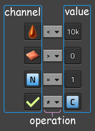
A condition holds three pieces of information: Signal channel, operation, and signal value. The different operations allow you to use the exact same signal in different ways. Condition operations are mathematical operations:
| = Equals | Value on this channel is exactly the selected | Can use non-numeric values |
| ≠ Does not equal | This exact value is not present on this channel | |
| < Less than | Number on this channel is lower than, but not, this number | Must use numeric values |
| ≤ Less than or equal to | Number is lower than, or exactly, this number | |
| > Greater than | Number on this channel is higher than, but not, this number | |
| ≥ Greater than or equal to | Number is higher than, or exactly, this number |
These operations give you a lot of versatility in examining signals.
If you want an object to function as normal unless switched off by a signal, you can use the ≠ does not equal operation. The condition will be enabled unless the exact value you have chosen appears on the channel.
The < ≤ less than and > ≥ greater than operations are useful for measuring the contents of a container. You can have a light turn on when the amount of copper in a chest goes below a certain number. Or, you could have a pump turn on when the amount of oil in a tank goes above a certain number, to ensure some machines get the oil by priority before releasing it to other factories.
This can also be useful for making sure boilers don't burn fuel unless accumulators are low:
Wire an accumulator to the offshore pump (they will have to be quite close together). Make sure the accumulator is in the electric grid the boilers are powering. Open the accumulator's circuit interface. By default, accumulators output their charge as a percantage on the [A] channel.
In the pump's circuit interface, set enabled condition [A] < 20
This works because accumulators all push their charge to the elctrical grid at the same rate. In a stable grid, if one accumulator is at 20% charge, they all are. You can try a lower number, but I reccomend 20% because it can take a while for turbines to get enough steam to produce power.
What is a combinator?
A combinator is an object specifically designed to work with the circuit network. It has no other use. There are three different types of combinator, specialised for a different purpose.
- Constant combinator: Sends whatever signal you tell it to into the circuit network. Can send multiple different signals at the same time. Does not need electricity, and can be switched off manually.
- Decider combinator: Compares two different signal inputs, and produces one signal output. Probably the most commonly used combinator, as it is both simple and versatile.
- Arithmetic combinator: A more complex decider combinator. Used for actual mathematics on signals.
This section focuses on the second in the list, the decider combinator, as it is complex enough to require an explanation, and is not the arithmetic combinator, which I do not understand (yet?)
You do not strictly need a combinator to use the circuit network. Most network-enabled entities are capable of performing their own decision operation via the "enable/disable" functionality (as in the offshore pump example above). A decider combinator is usually only needed in more complex situations. In particular, if you need to make a decision based on two separate signals, you will need at least one decider combinator, probably two or three.